
Engineering Selection Methodology for Industrial Chains: A Comprehensive Guide for Mechanical Design Engineers
6/8/20264 min read
Determining Transmitted Power and Speed
In the process of selecting an appropriate industrial chain, mechanical design engineers must first determine the transmitted power and speed required for their specific applications. This critical initial step involves calculating the power in watts, establishing the necessary gear ratios, and understanding the implications of these parameters for chain selection.
The power transmitted by a mechanical system can be calculated using the formula: P = T × ω, where P indicates power in watts, T is torque in newton-meters, and ω is angular velocity in radians per second. When assessing an application, engineers should consider the maximum and average loads that the chain will encounter, ensuring the selected industrial chain is capable of handling these requirements without failure.
Furthermore, the calculation of speed is also vital, as it directly influences both the efficiency and the operational lifespan of the industrial chain. An understanding of the gear ratio, defined as the ratio between the rotational speeds of the input and output shafts, is essential in this regard. The gear ratio can be calculated using the formula: Gear Ratio = Input Speed / Output Speed. Establishing the correct gear ratio ensures that the power transmitted aligns with the desired speed outputs critical in many industrial applications.
As an illustration, consider a conveyor system in a manufacturing plant that requires a speed of 2 meters per second and a load of 1500 newtons. By calculating the required power and determining the suitable gear ratio based on the expected operational conditions, engineers can select a chain that optimally meets these constraints. This careful analysis not only enhances performance but also contributes to the longevity of the system, preventing unnecessary downtimes and maintenance costs.
Selecting Chain Type per Application
In the realm of industrial applications, choosing the appropriate type of chain is critical for ensuring optimal performance and reliability in mechanical designs. Various types of industrial chains are available, and the selection often depends on the specifics of the application, including the nature of the load, operational environment, and individual requirements.
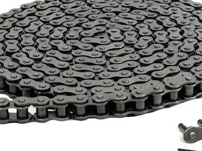
One of the most commonly used chains is the roller chain. Characterized by its flexibility and strength, roller chains are frequently employed in applications requiring power transmission, such as in manufacturing equipment and conveyor systems. Their design allows for smooth operation over sprockets, making them ideal for scenarios that demand dynamic movement.
Another option is the block chain, which is typically used in hoisting applications. These chains offer robust support for heavy loads and are designed to handle significant stress. When choosing a block chain, factors such as load weight, lifting height, and environmental conditions must be considered to ensure functional integrity.
For applications specific to conveyor systems, specialized chains designed for transporting materials should be examined. These may include slat chains or modular plastic chains, which cater to diverse industries by facilitating the movement of various products through assembly lines. The selection criteria for these systems often include load-bearing capacity, ease of maintenance, and adaptability to different products.
Real-world examples illustrate the necessity of selecting the right chain type. For instance, the food processing industry frequently utilizes stainless steel roller chains due to their resistance to corrosion and hygiene requirements. Conversely, automotive manufacturing may benefit from heavy-duty block chains to facilitate efficient lifting and lowering of components. Each choice impacts the overall operational efficiency and longevity of the system.
Calculating Required Tensile Strength per ASA/ANSI B29.1
The selection of a suitable industrial chain necessitates a thorough understanding of its tensile strength, particularly in compliance with the ASA/ANSI B29.1 standards. This section outlines the methodological approach to calculate the required tensile strength, a critical factor ensuring reliability and safety during operations.
To begin, it is essential to account for various load characteristics that the chain will experience in its operational environment. These characteristics include dynamic loads, static loads, and any additional factors that could contribute to stress on the chain. The total load must be considered to accurately determine the required tensile strength.
An essential aspect of this calculation is the incorporation of a safety factor, which ensures that the chain can withstand unexpected increases in load or operational stresses. Typically, safety factors can range from 1.5 to 3.0, depending on the application of the chain and the criticality of the load it supports. A higher safety factor is often advisable in applications where failure could result in significant consequences.
For illustrative purposes, let us consider a simple example: assume a chain is required to support a load of 1000 pounds with a safety factor of 2.0. The required tensile strength can be calculated using the formula:
Required Tensile Strength = Load × Safety Factor.
In this case, the tensile strength would be:
Required Tensile Strength = 1000 pounds × 2.0 = 2000 pounds.
This example highlights the fundamental approach to ascertain the tensile strength of a chain based on operational loads and safety considerations as per the ASA/ANSI B29.1 standards. By carefully calculating the required values, mechanical design engineers can ensure that the selected chain will perform effectively throughout its service life, mitigating risks associated with mechanical failure.
Determining Number of Teeth on Sprockets for Optimal Wrap Angle and Calculating Center Distance and Chain Length
When designing mechanical systems involving industrial chains, one vital consideration is determining the number of teeth on sprockets. The optimal number of teeth is essential to achieve the desired wrap angle, thus maximizing the efficiency and ensuring the longevity of the chain drive system. A higher number of teeth reduces the wrap angle, which minimizes wear and enhances performance.
The wrap angle is calculated based on the number of teeth on the sprocket and the radius of the sprocket. As a general guideline, a minimum wrap angle of 120 degrees is recommended to maintain effective power transmission. The use of the formula:
Wrap Angle (in radians) = 2 * Arc Cosine((D – d) / (2 * R))
where D is the diameter of the driving sprocket, d is the diameter of the driven sprocket, and R is the center distance, can provide critical insights on how the number of teeth affects the overall system performance.
Once the number of teeth is determined, the center distance and chain length can be calculated. Center distance is defined as the distance between the axes of two sprockets. It plays a crucial role in ensuring optimal tension in the chain, as excessively long or short distances can lead to premature chain fatigue. The formula to calculate center distance is:
Center Distance = (Number of Teeth on Driver + Number of Teeth on Driven) * Pitch / (2 * Sin(Wrap Angle / 2))
To calculate the chain length, the following formula can be used:
Chain Length = (2 * Center Distance) + (Driver Teeth + Driven Teeth) * Pitch
In practical scenarios, let's consider an example with three driven sprockets. By applying these formulas, a mechanical design engineer can easily verify optimal arrangements to enhance performance and ensure efficient operation of chain systems.
Quality
Expert chain manufacturing with 20 years experience.
GET IN TOUCH
Tel:+86-571 88065675 | +86-571 88842852
E-mail:oceanindustry@vip.163.com
Fax:+86-571 88844378
Address:4th Floor, Block 2, Qianjiang Century Industrial Park, 2327 Hongning Road,Ningwei Town,Hangzhou, China
© 2005. All rights reserved.
An OIC Group company